


In this article
Start at the tooth contact
A leaking coupling can still have grease inside its cover. Both observations can be true while the tooth contacts receive too little lubricating oil.
Grease contains base oil held in a thickener structure. The oil has to reach the working surfaces. Finding material inside the cover leaves that job unproven.
At the authorised maintenance stop, recover the lubricant identity and filling history before adding more. Inspect the leak, seals, teeth and alignment against the maker's instructions. The leak needs an explanation, as well as a refill decision.
What is reaching the mesh?
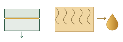
The oil film separates loaded, moving metal surfaces.
Thickener and oil can redistribute under rotation.
Retained material alone cannot confirm adequate lubrication.
Mobil's flexible-coupling guide describes a particular concern with general-purpose grease: under centrifugal forces, denser thickener can collect near the outer tooth mesh while oil separates towards the centre. That can leave material at the teeth with inadequate oil supply.
The appearance of a leak does not establish that this happened. It gives the team a reason to inspect the lubricant and the coupling together.
Give the reviewer the duty the coupling actually runs
Two pieces of information belong beside the lubricant recommendation: the coupling's identity and its operating range. Include maker, type, size and orientation, then record sustained slow operation as well as normal and maximum speed.
At a fixed radius, a = rω². Diameter matters too. This explains the centrifugal loading; it does not calculate an allowable speed or grease life.
A variable-speed drive can spend hours below its normal duty. A recommendation checked only against the motor nameplate misses that part of the application.
The GEARex lubricant table defines a speed and circumferential-speed range for its listed products and directs users to KTR when duty differs. Its requirements belong to that design. Use the equivalent instructions for the actual coupling.
“Motor: maximum rpm.”
“Coupling maker, type, size and orientation; normal range, sustained low-speed duty and relevant temperatures.”
Next, compare the whole lubricant specification. An NLGI grade describes consistency. It does not name the base-oil viscosity or establish centrifugal separation resistance. ASTM D4425 evaluates a grease's tendency to separate under high centrifugal forces. Ask for relevant product evidence alongside the coupling maker's approval.
If the replacement product or changeover is unresolved, keep the task open for the responsible engineer or supplier. The grease changeover guide explains why product selection and introduction need separate decisions.
Carry “per half” all the way onto the task
A copied quantity can look exact and still lose its meaning. The number needs its unit, the arrangement it applies to and the part of the assembly it covers.
The quantity has a scope.
For the listed two-half arrangement, copying Q as the whole-coupling quantity loses one half's allocation.
KTR's standard quantity table is explicitly per coupling half. Vertical or special arrangements require the applicable drawing or consultation. A route sheet that retains the value but drops those qualifications transfers the decision to the technician.
The method matters with the quantity. KTR also describes the plug positions and vent opening for its design. Attach the corresponding filling, venting, cleaning and inspection instructions for the actual model instead of issuing “top up coupling”.
Release a job someone can perform and verify
A useful instruction survives the trip from engineering to the machine. Before release, the planner should be able to point to the approved source for each of these fields.
- Unit and duty
- Asset, maker, type, size, orientation, speed range and relevant temperatures.
- Product
- Exact lubricant, supporting approval and any agreed changeover method.
- Quantity and method
- Value, unit, per-half or whole-assembly basis, filling and venting arrangement.
- Inspection and closeout
- Applicable seal, tooth and alignment checks; findings, action owner and next review.
Download the blank coupling job record CSV fields for a planning or maintenance system.
Complete the work under the site's isolation procedure. Keep what was found separate from what was changed. If the leak returns, the next review needs the previous lubricant, quantity, method and inspection findings, rather than another untraceable addition.
The useful final entry explains why that coupling received that lubricant, in that quantity, by that method. It gives the next maintenance stop something better to work from than the amount of grease visible in the cover.
Sources and method
Original diagrams explain coupling lubrication and a quantity-basis example. Q is a symbol for the equipment maker’s quantity, not a dose. Manufacturer instructions apply to their named designs.
- GEARex operating and assembly instructions, 40310 EN, edition 21, KTR: grease recommendations, quantity and filling, sections 5.2 to 5.4; service and inspection, section 7.
- Introduction to flexible couplings, Mobil: gear-coupling lubrication and movement of grease under rotation.
- ASTM D4425-24: public description of the centrifugal oil-separation test. The full paid standard was not used.
Bring the coupling identity, duty and current instruction to the discussion.